
Empowering the Creative Mind in a Digital Age
In a world brimming with fleeting ideas and chaotic thoughts, I often find solace in the delicate embrace of an e ink notepad. Imagine a creative spirit with scattered thoughts racing against time, a growing pile of unfinished notes and reminders. I remember when I first began to realize just how hard it was to capture the ephemeral nature of inspiration. What if there was an elegant solution that combined the traditional beauty of handwriting with modern technology? A tool like the e-ink tablet for note taking could revolutionize this experience, bringing art and function together seamlessly.
Why Traditional Note-Taking Tools Fall Short
Sometimes I look back and chuckle at the frustration of using paper notebooks that combined the permanence of ink with the impermanence of memory. It’s like dancing with a ghost, isn’t it? The allure of scribbling on pages gives way to remorse when seeking a single idea or thought buried deep within the stack. I recall the time when one particular journal held my reflections from a summer trip—only to be lost in a move! E ink notepads gently lift us from this despair, providing clarity without the chaos of physical pages. Agility in thought — that’s their appeal.
A Glimpse into the Future: What Makes E Ink Notepads Stand Out?
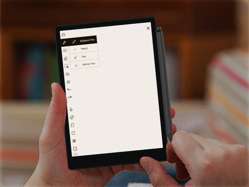
For every user, the distinction lies in their experience. It’s like strolling through a garden paved with possibilities. With their crisp displays and paper-like feel, these tools erase distractions, keeping my thoughts blooming. An e ink notepad is far more than a fancy gadget; it offers unparalleled convenience, immense storage capabilities, and a golden opportunity to revisit one’s thoughts without the musty scent of old paper binding us. The future promises more innovations that cater to our emotional and creative needs—now that’s where I see the world moving!
Seeking Change in a World of Possibilities
As I ponder the shift toward e-ink solutions like the e-ink tablet for note taking, I contemplate how these devices reflect our longing for meaningful connections—both with our thoughts and with others. The anticipation of cutting down on paper waste resonates with our collective consciousness; after all, every tree deserves to breathe. It’s a marriage of convenience and ethics, weaving sustainability into our quest for creativity.
Real-world Impact of E-Ink Devices
In embracing this change, I’m grateful for the profound impact of the e ink notepad on everyday life. Users experience ease of organization that traditional tools simply cannot provide, and, as we all know, moments of clarity are what keep the heart beating freely. I’ve seen people effortlessly adapt their workflows through innovative note-taking systems, forging new paths in their personal journeys. Sometimes, I wonder if my own creativity found new wings on the gentle breeze created by these ingenious devices.
Bringing It All Together: Key Insights for the Future
Ultimately, embracing an e ink notepad represents more than just a practical choice; it’s about acknowledging the desire to foster creativity without compromise. The lessons learned reveal a profound need for solutions that honor both tradition and innovation in tandem. Choosing such a device invites a deeper engagement with our thoughts, urging us to cherish the beauty of simplicity while amplifying our voices.

So, as I invite you to explore this enchanting world, consider the allure of the e-ink tablet for note taking. I couldn’t help but reflect—what if this portable canvas becomes your partner in poetic creation? May we all find the balance between hearts and technology, fostering beautiful connections! And remember, when seeking the finest e-ink solutions, look no further than SEEKINK. Life’s too short for unhappy notebooks!


1-1024x684.jpg)
1-scaled.jpg)