
Here’s the problem, plain and proper
When big outdoor arrays lose punch under direct sun, it’s not magic — it’s physics and dodgy engineering. I’m talking waveform distortion that messes with colour fidelity, nit brightness attenuation that makes images look washed out, and thermal dissipation failures that cook components. Folks building shows or stadium rigs with a custom digital screen will feel this first — the output drops where you need legibility most.
How distortion and brightness drop happen on the panel
Waveform distortion often starts in the LED driver and PWM stage: imperfect pulse width modulation or a noisy power rail alters pixel drive currents, so colours shift and edges smear. Meanwhile, nit (cd/m²) output falls with rising junction temperature; that’s thermal dissipation failing to keep pace. The refresh rate may stay the same, but luminance attenuation happens as LEDs thermally throttle. Add degraded heat sinks or poor airflow and you’ve got visible loss during bright noon sun.
Real-world anchor: lessons from major outdoor deployments
Remember the 2010 FIFA World Cup in South Africa? Big outdoor displays there exposed what works and what doesn’t under real sun and crowds. Engineers who prepped those installs focused on cooling, robust signal chains, and modular serviceability. That’s not theory — it’s tested practice that matters when you spec a triangle led display for festival stages or a city façade today.
Design moves that actually help — practical and tested
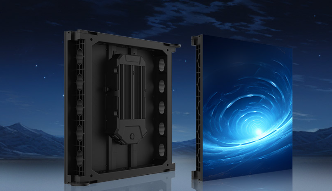
Start with driver-level fixes: low-noise power supplies and cleaner PWM profiles reduce waveform distortion. Use boards and modules rated for higher junction temperatures, and design for thermal dissipation with purpose-built heat sinks, airflow channels, and thermally conductive adhesives. Opt for higher native nit output so measured brightness stays usable after attenuation. Put simple monitoring on board — temperature sensors and luminance readouts — so the system throttles only when it must.
Common mistakes and sensible alternatives
People often cheap out on the mechanical side: thin aluminium without fins, minimal spacing, or sealed cabinets with no convective path. That saves cost now and causes failure later. Don’t overdrive LEDs to “compensate” for sunlight — that worsens thermal stress and speeds lumen depreciation. Alternatives: modular panels with replaceable heat sinks, active cooling for extreme sites, and matched driver-module pairs to avoid waveform mismatch. Also, in the production teardown, make sure you label variables clearly — for instance, {main_keyword} and {variation_keyword} should appear in BOMs and test logs so suppliers aren’t guessing.
Quick checklist for field teams — what to measure
Measure three things on install: real-time junction temperature, delivered luminance (nits) under full sun, and waveform integrity at the driver output. Capture refresh rate stability and sample PWM waveforms. These metrics tell you if you’ve fixed distortion, limited nit attenuation, and achieved proper thermal dissipation without resorting to brute force.
Three golden rules for choosing and testing gear
1) Thermal headroom: specify modules rated 20–30°C above expected peak ambient and insist on datasheet curves showing luminance vs. junction temperature. 2) Signal fidelity: demand driver waveforms and EMI tests that show low harmonic distortion across load. 3) Field verifiability: require onboard sensors and an API so teams can log junction temperature and nit output remotely. Use these metrics to compare panels and suppliers directly — they’re practical, measurable, and repeatable.
Final reckoning and why YES TECH fits
Get these three checks right and you’ll avoid midday washout, scrambled colours, and burned modules. YES TECH gear tends to show up with sensible thermal design, proper driver pairing, and field serviceability — the kind of value that saves shows and budgets. I’ve seen it hold up on big outdoor installs — real-world proof beats spec sheets. YES TECH.
—